Capacitor Failure Analysis
Multilayer Chip Capacitors (MLCCs), Tantalum Capacitors, Aluminum Electrolytic Capacitors, Film Capacitors, Failure Analysis
At SEM Lab, Inc. we perform capacitor failure analysis for several types of capacitors including: Multilayer Chip Capacitors or MLCCs, Tantalum Capacitors, Aluminum Electrolytic Capacitors, and Film Capacitors. The differences in capacitor construction are described below as well as some common failure mechanisms observed during capacitor failure analysis. Failure analysis of capacitors often focuses on the quality of construction techniques used during the manufacture of these devices.
Multilayer Chip or CERAMIC Capacitor (MLCC)
Multilayer chip capacitors (MLCCs) are usually the capacitor of choice when low value capacitances are needed. MLCCs construction consists of a ceramic block with parallel rows of sintered electrodes within, creating alternating layers of ceramic and metal. These metal electrodes come to the surface at the ends of the ceramic block and attach to connecting terminals.

Failure analysis of this MLCC showed fused nickel electrodes and barium titanate dielectric and suggests that a large current flowed through the short during the failure event.
Failure analysis of MLCC shows distorted electrodes, which suggests that capacitor manufacturing process was not optimized.

Multilayer chip capacitors (MLCCs) can fail due to a manufacturing defect known as Knit Line Fracture or Failure, which is a lamination defect causing separation on internal layers. More failure analysis of MLCCs can be found here.

Failure analysis of MLCC shows a flexure crack.
Tantalum Capacitor
A Tantalum capacitor is an electrolytic capacitor. A piece of tantalum metal acts as an anode and is covered by an insulating oxide layer that forms the dielectric. This is surrounded by liquid or solid electrolyte which acts as a cathode. Tantalum capacitors are usually chosen when high capacitances per volume and lower weight are required.
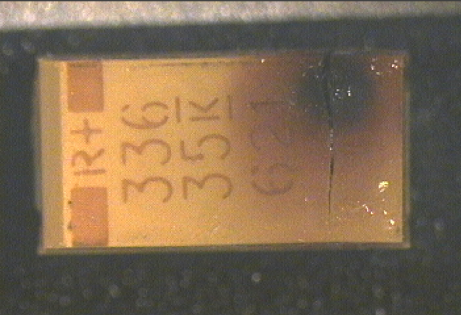
Optical image of the top of a Ta Capacitor. Capacitor failure analysis revealed a burn mark and fracture visible on this surface..

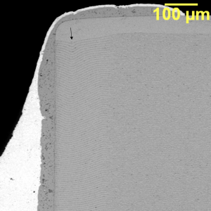
SEM image of the microsection of a Ta Capacitor. The primary capacitor failure site is associated with the edge of the slug near the lead attachment at the cathode.

Tantalum-oxide dielectric layer (arrows) in a Ta capacitor.

The MnO2 deposit region of a Ta Capacitor. The region appears normal though slightly granular near the outer layers of the deposit.
Aluminum electrolytic capacitor
An aluminum electrolytic capacitor consists of an anode made of thin aluminum foil with an etched surface. Anodization forms a very thin insulating layer of aluminum oxide on the aluminum that acts as a dielectric. Aluminum Electrolytic Capacitors provide the largest capacitance values per unit volume compared to ceramic and plastic film capacitors.

A dissected Aluminum Electrolytic Capacitor.

The FTIR spectrum of the electrolyte inside an aluminum electrolytic capacitor can be used to determine the amount of water in the electrolyte, which to a large extent determines its electrical conductivity and therefore the equivalent series resistance (ESR) of the capacitor. The FTIR spectrum can also be used to determine the amount of depolarizer in the electrolyte, which is a factor in the expected life of the device.

An aluminum electrolytic capacitor after unrolling. It shows internal the connection of the negative terminal (cathode) to the cathode foil.
Film capacitor
Film capacitors use a thin insulating plastic film as the dielectric with evaporated aluminum conductor on one side of the film. This metallized film along with a counter electrode is rolled into a cylinder. Metal terminations are then added and the assembly is mounted into a protective case. Film Capacitors are chosen when low cost, stability, and low inductance are required. Some types of film capacitors, are metallized polyester, polypropylene, PTFE or polystyrene film. More detail on failure analysis of Film Capacitors can be found here.

Secondary Electron SEM image of the end of a film capacitor roll.

A thicker deposit of evaporated aluminum is applied to one edge of the film to withstand the thermal exposure during flame-spray termination of the capacitor layers during fabrication. The Al-peak is higher in EDS spectra of thicker aluminum deposit and can be used as a measure of aluminum thickness.

Failure analysis of a capacitor microsection at the end cap showing a region where the end cap is not connected to the capacitor plates, which would likely result in lower than expected capacitance and possible capacitor failure.

The flame-spray end cap is zinc. The termination to the zinc end cap is eutectic tin-lead solder.